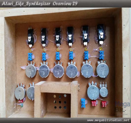
Top Pannel Placment
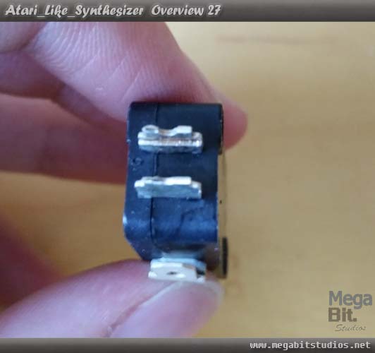
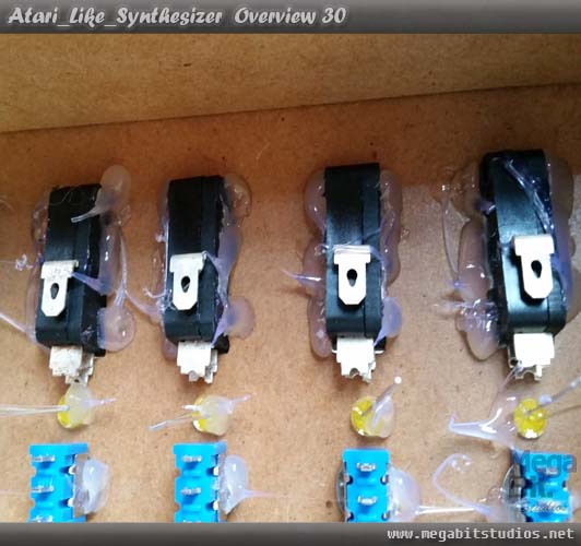
Trim the Micro switch SPDT down so they will fit in behind the LEDs.
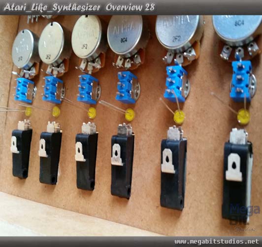
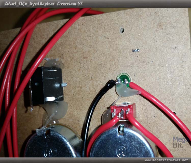
Ok line everything up so that it is straight switches, pots and LEDs now hot glue everything in to place start with the Micro Switch SPDT make sure to glue them in well because, it will be the only thing holding the switches in place, put a small dab on all the pots, switches and LEDs to hold them in place so they don't move .
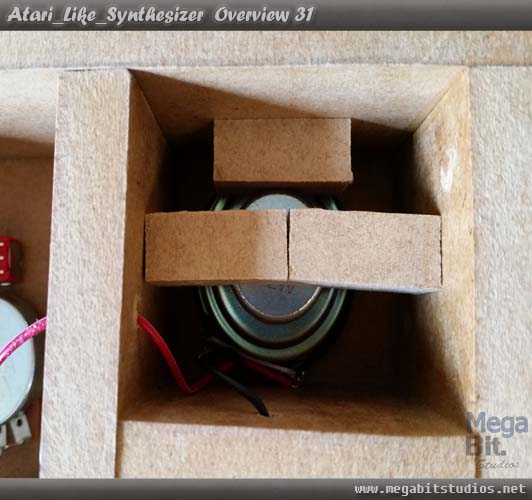
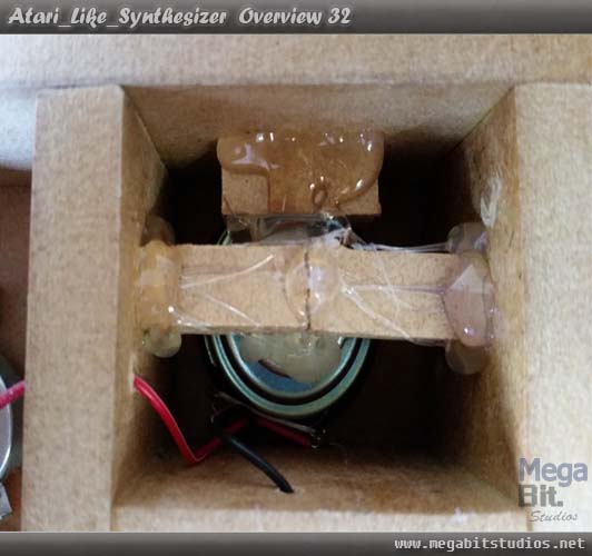
Now line up the speaker in the speaker box then put the small spacer bits of wood on the back of the speaker and hot glue them in to place, feed the wire threw the holes on the sides.
Making The Main Board
Ok now to create the circuit board to drive the whole project, use the circuit diagram and circuit board design Click Here, use your preferred method of creating a circuit board may it be a prototype board, PCB etching or milling. My preferred method is to Etch the board Click Here to learn how to etch a PCB.
The Finished Boards
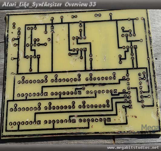
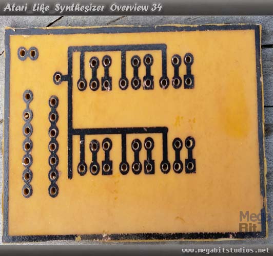
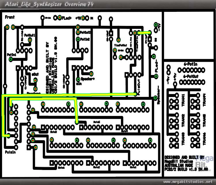
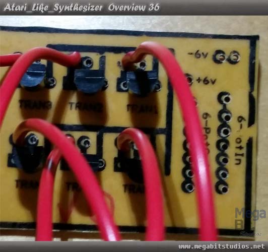
Once you have the board created solder all of the components to PCB1 & PCB2 along with 300mm of 13 black and 26 red cable for all of the inputs and outputs (find diagram below to assist with the wire colours and inputs and out puts the Yellow Line indicates where to run the 3 jumper cable).
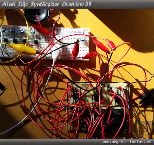
When everything is together, test that the circuit is functioning correctly & lacquer PCB1.
Then cut 6 Red wires 50mm long and solder them to the far left pads for each of the transistors.
Wireing & Such Fun
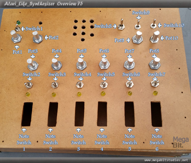
Make sure you check the switch direction before soldering, all steps will assume you know the switch connectors orientation. Sitting the front panel face down on a empty container for soldering and Velcro tape the PCB1to the middle of the main box along the far edge, also find a diagram below to help identifying the switches and pots.
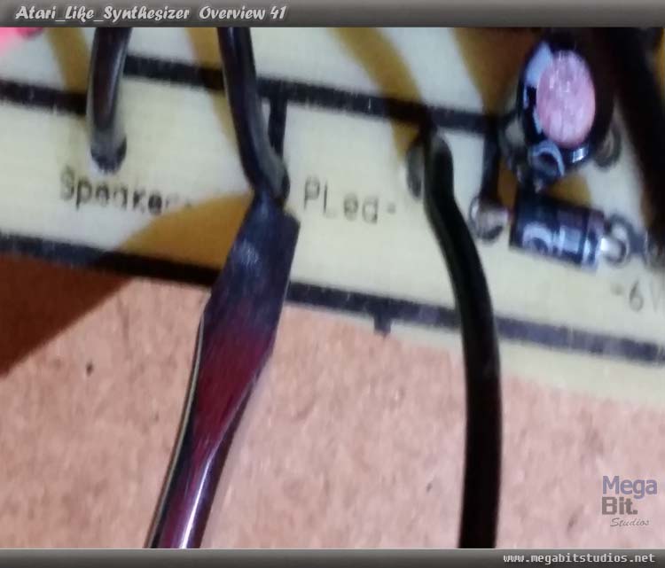
Solder the power switch line for PCB1 to switch1 centre connector.
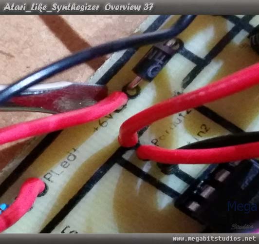
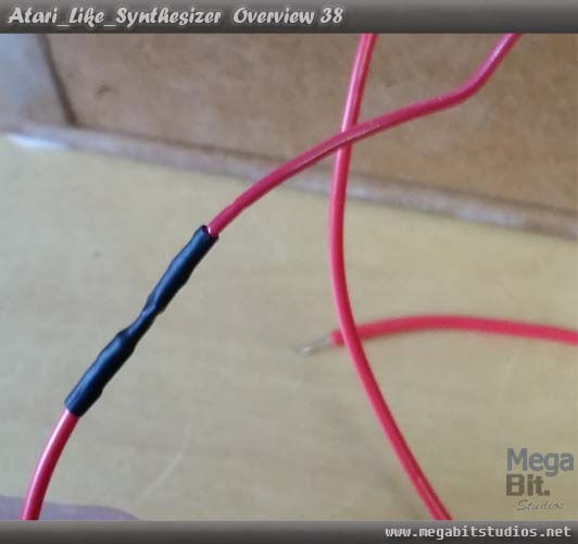
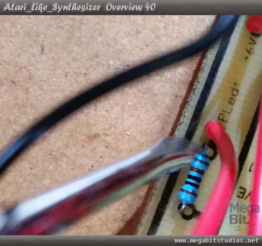
Solder an extra wire from the battery clip that is 250mm, heat shrink the joint and solder the other end to switch1 with left being the on position.
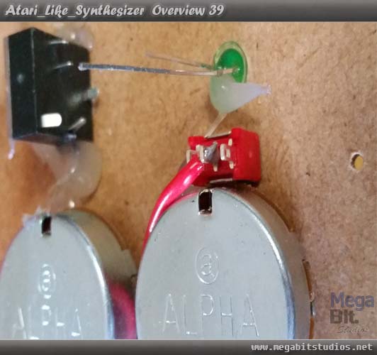
Solder the positive line for the power led to the positive leg on the Led and do the same for the negative.
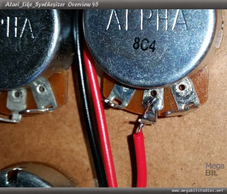
Cut 7 red wires 150mm long then solder all of them to PCB2 6-potIn once all are soldered in to place, trim the excess wire off the solder joint.
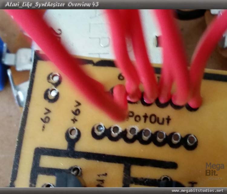
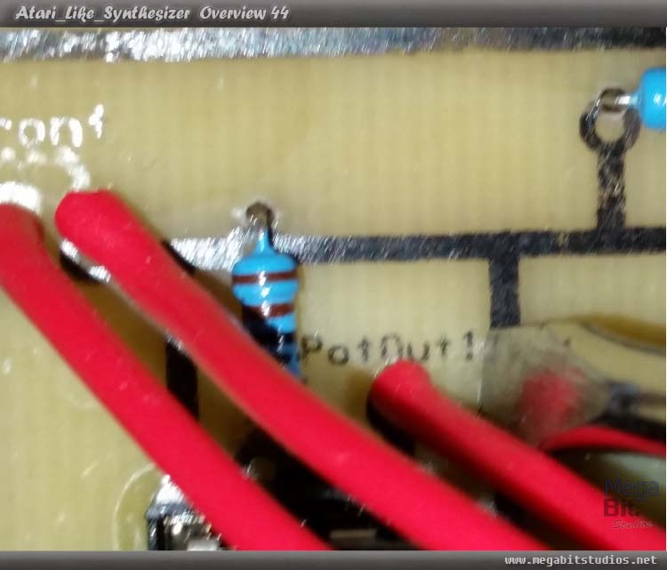
Now put PCB2 in to place on top of pot 5 & 6 use a small piece of masking tape to hold it in to position for the moment, solder PotOut1 from PCB1 to the centre of Pot1.