More Soldering
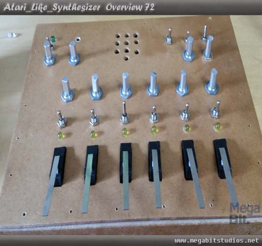
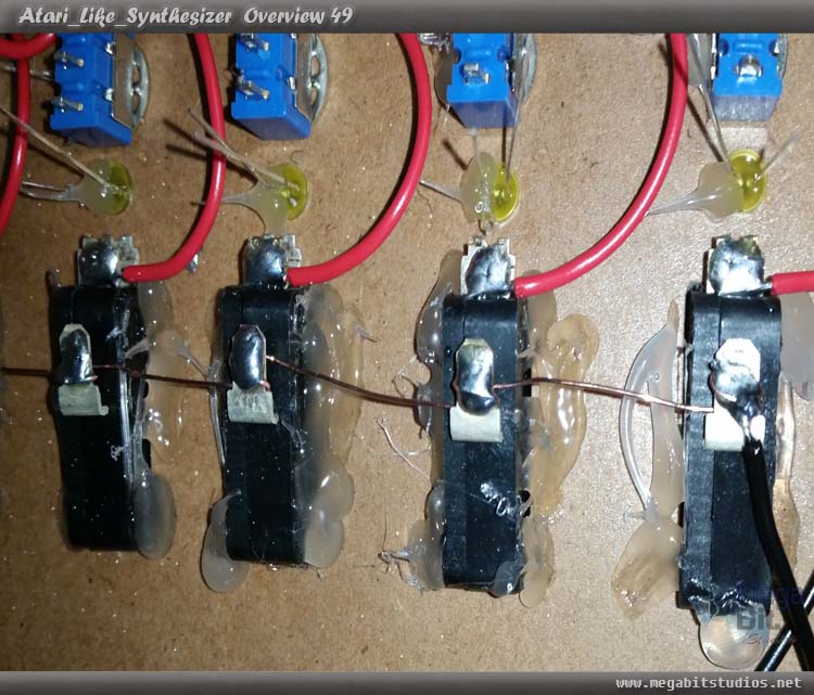
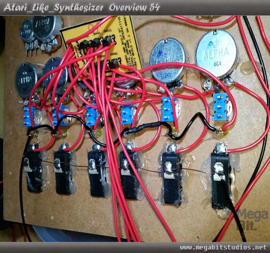
Trim the Micro switch SPDT down so they will fit in behind the LEDs.
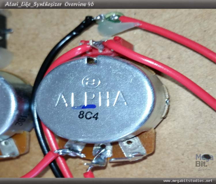
Cut and solder the rest of 6pinin on pcb2 to the centre of Pots 3,4,5,6,7,8.
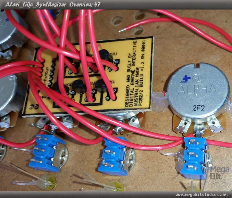
Now cut 6, 65mm long red wire to go from the right of the same pots to the normally open lug on the note switches.
From the bottom lug of the note switch, solder all of them together with a piece of single core wire, solder the wire from the PotIn1 on PCB 1 to the top lug on NoteSwitch1.
Solder a positive 9V feed cable from PCB1 to the transistors +9v on PCB2, from the pulse out on PCB1 for the LEDs going from top to bottom, the top wire the first wire cut and solder to the centre pin for Tran4 on PCB2.
The second wire down cut and solder to centre of Tran3
The third wire down cut and solder to centre of Tran1,
The fourth wire down cut and solder to centre of Tran2,
The fifth wire down cut and solder to centre of Tran6.
Now to solder the last wire to the Centre of Tran5 which is the wire on the other side.
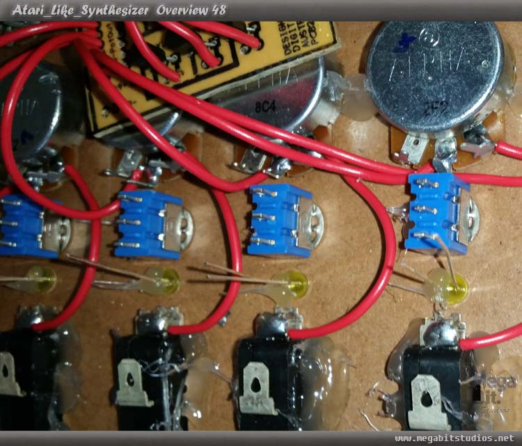
Now to solder wires from the transistors left contact on PCB2 long enough to go to all of the note LEDs, this part is simple just follow the order of the LEDs to transistor numbers for example Note1 Led1 will connect to transistor1 wire and so on.
Then solder a wire from all of the negative leg of the LEDs to a negative wire from PCB1 you will need to extend this wire, finally trim all of the Led Legs
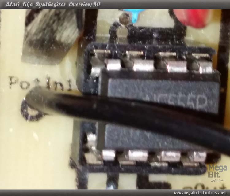
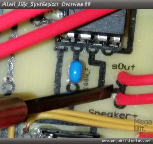
Go to PCB1 First 555 Timers sOut and Speaker+ now these wire will be soldered to switch 9 the double pole double throw in the configuration up is on solder sOut to the centre of pole one and the speaker+ to the up potion of the second pole.
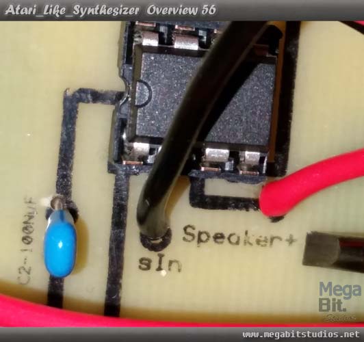
Now on the second 555 timer locate the sIn and Speaker+, for the Sin you want solder to the switch in the down passion on the first pole (that has sOut connected to the centre), the down position on the second pole connect to Speaker+.
From switch 9 pole 2 (speaker+) centre solder a wire to the centre of Switch 8 and then solder a 10uf capacitor to one side and a 470uf capacitor to the other side with the positive leg to the switch.
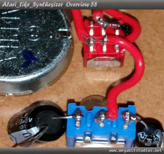
From the negative side of the two capacitors we just soldered solder a wire from both of them to the centre of Pot 2( make sure to leaves room for the speaker box).
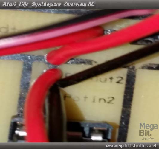
From 555 timer 2 we want to solder the potOut2 wire to the centre of pot 9, potin2 solder it to the left leg on the pot9.
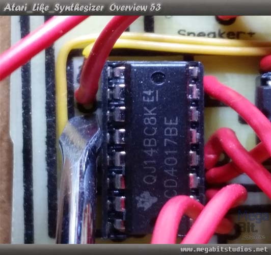
From 555 timers 3 solder the 2 wires from pin to switch 10 so that down is ON this switch will turn on the 555 timer and CD4017.
Do the same with the CD4017 on pole, 2 its positive power wire is located under the front label to left of pcb1.
From the wire soldered to resistor 3 (this is fixed on the new PCB revision it now has a solder Pad) on the third 555 timer solder this to the centre of pot10 and the wire from the same timer from leg 3 on the IC to the left of the same pot.
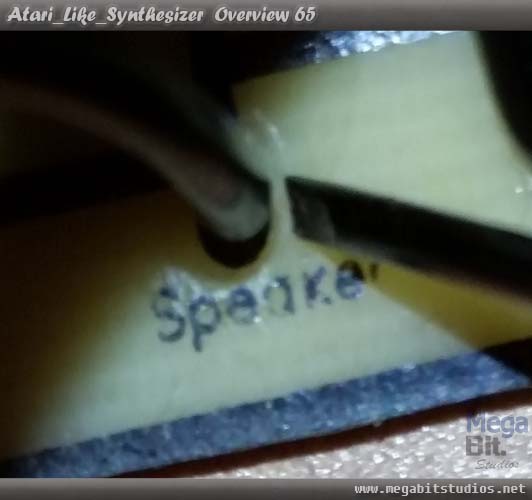
From speaker- solder this to the negative wire of the speaker and heat shrink it.
The Home Stretch
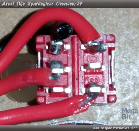
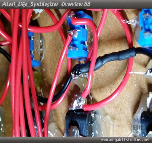
Now solder all the relays to their accompanying notes first start with relay1 the top left one this one will connect to note 3 so solder the red wire to the centre of switch 4 above note 3, solder a wire from the contact for the down potion on switch4, to the back of note 3 Micro Switch SPDT, solder the black wire from the first relay to the top connector on note 3 Micro Switch SPDT, Now repeat this for all of the other relays and notes use the circuit board design as a reference to what relay goes to what note.
The final part the hardest part, now from pot 2 solder a short black wire to the right leg of (the negative) of the power led.
Now to work out the pin out for the 3.5mm audio jack this many vary to your one so grab your malty meter out and work out the pin out, we want it so that when the 3.5mm jack in inserted the speaker disconnects and the audio from the synth goes to the 3.5mm jack. Once you have this worked out solder a wire from Pot2 left leg (This is the primary audio from the synth) to the 3.5mm Jack to is correct leg. Solder the negative leg of the 3.5mm to the power LEDs negative leg, once you have The switched wires worked out solder a wire from the 3.5mm socket to the positive of the speaker. (Alternatively if you don't want the 3.5mm Socket solder Pot2 left leg to the speakers Positive wire)
Now we can power it on and test if it works don't for get to put something under pcb2 so it doesn't short out to the Pots.
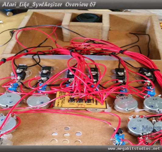
Now to clean up some of the wiring make it nice and neat use some zip ties togroup up the cabling.
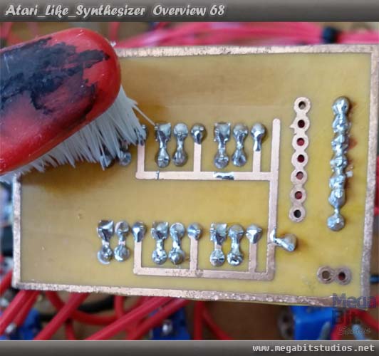
Clean PCB 2 with an old tooth brush and isopropyl alcohol.
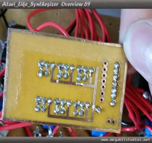
Now to lacquer PCB2 tape two piece of a4 paper together and cut a square out of the middle about the size of the PCB then masking tape it to the PCB, simply lacquer the PCB with a minimum of 3 coats. once dry remove the paper and check that the back isn't conductive then Velcro tape PCB 2 to the back of pot5 & 6.
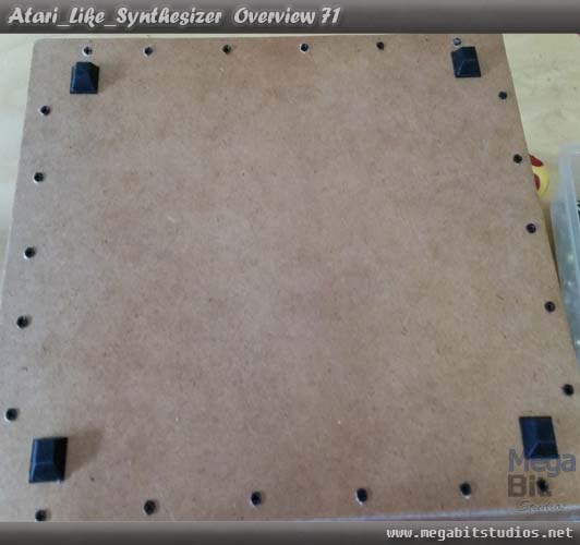
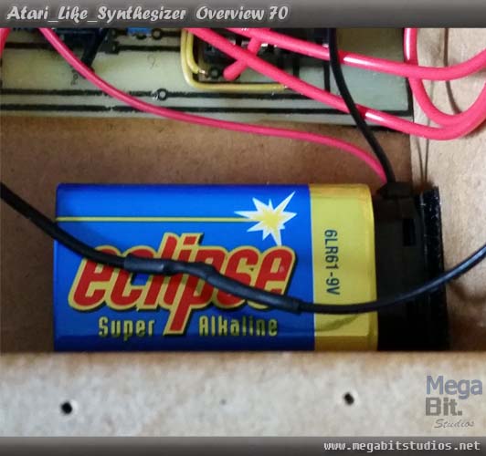
Velcro tape the top of the battery clip to the bottom of the case.
The Last Step & We Are Ready For Chip Tunes.
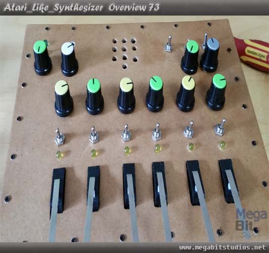
Finally, folder everything back together and check the clearances, put in all of the screws 2mm by 10mm screws on the top and bottom, line up all of the faces on the knobs, put all of the knobs on, stick the 4 rubber feet on the bottom, power it on and enjoy.